Back to Main Overview

Hardware Engineering
Projects

STM32 IoT Nixie Tube Clock (180V Boost DC-DC)

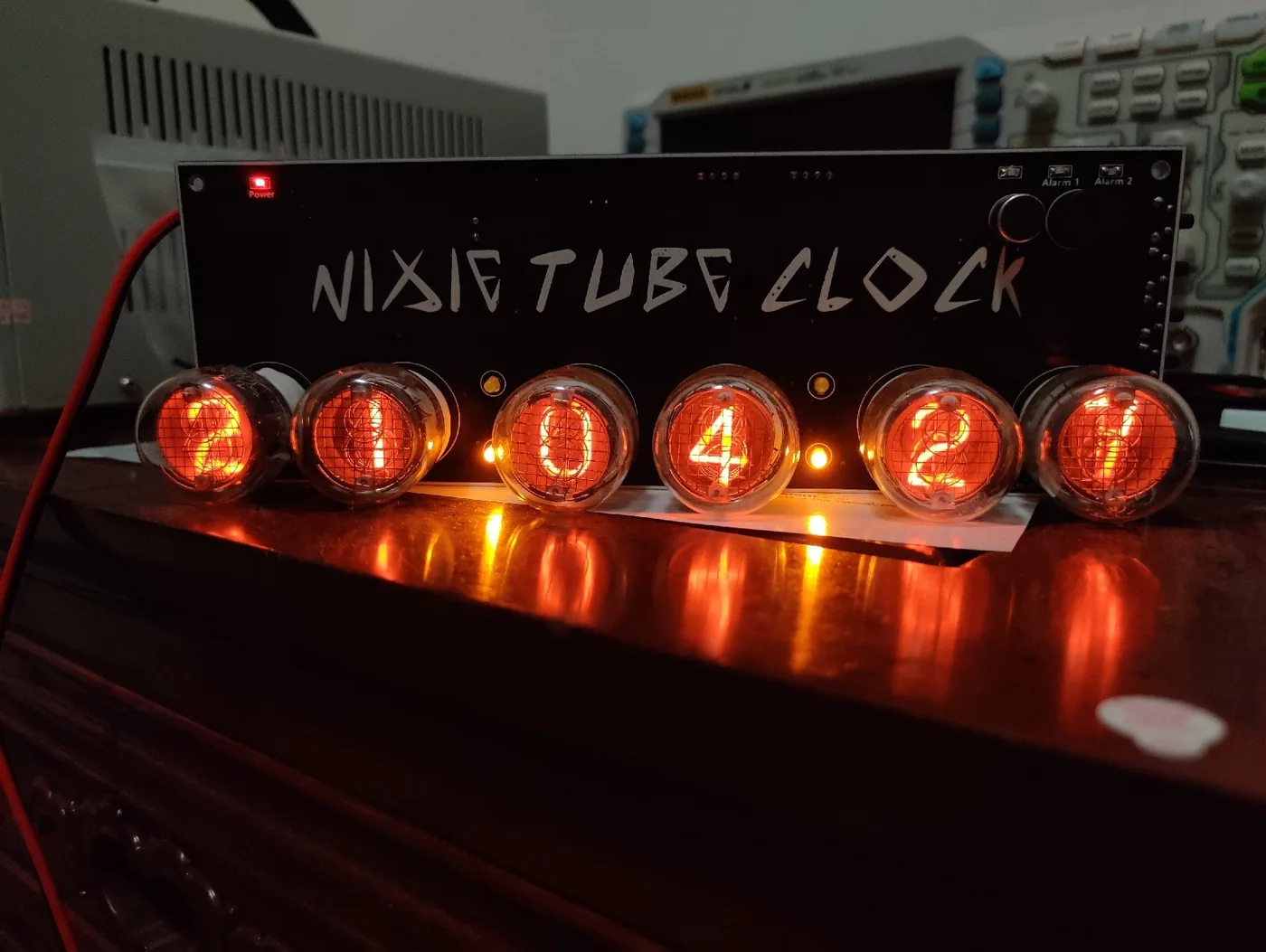
STM32-based retro Nixie tube clock utilizing QS-30 tubes and custom 180V DC-DC boost circuitry. Features built-in microphone acoustic threshold wake-up to conserve tube lifespan, DS3231 RTC coin-cell backup, Wi-Fi NTP time synchronization, smartphone settings, and custom 3D printed enclosure.
ENGINEERING DESIGN OVERVIEW

A high-precision vintage Nixie tube clock designed and assembled from bare silicon to the enclosure. Utilizes a custom-engineered DC-DC boost topology to step up a 12V input to 180V DC for ionizing the neon gas in QS-30 tubes. To significantly extend tube lifespan, the unit incorporates an onboard microphone that keeps high-voltage generation dormant until ambient sound exceeds a calibrated threshold. Features a high-precision DS3231 hardware RTC with coin cell battery backup to maintain time accuracy during outages, paired with Wi-Fi connectivity for periodic NTP synchronization and smartphone web/BLE user controls.
KEY IMPLEMENTATION HIGHLIGHTS

Designed high-voltage 180V DC-DC boost converter power supply stage with safety current limiting to drive QS-30 Nixie tubes
Integrated built-in microphone sound activation: display stays dormant and only wakes when ambient noise exceeds a threshold, conserving tube lifespan
High-precision RTC timekeeping backed by CR2032 coin cell + automatic Wi-Fi NTP time calibration
Custom smartphone web portal and connectivity for adjusting backlight effects, sound sensitivity threshold, cathode poisoning prevention cycle, and alarm functions
Designed custom 2-layer PCB layout in EDA, hand-assembled all SMD/through-hole components, and designed custom 3D-printed enclosure

MEASURED HARDWARE SPECIFICATIONS

High-Voltage Stage Custom 12V to 180V DC-DC Boost (HV57708PG Driver)
Nixie Tubes & Lifespan QS-30 Tubes, Built-in Mic Sound Threshold Activation
Microcontroller STM32 Series ARM Cortex-M
Timekeeping & Sync DS3231 RTC + Coin Cell / Wi-Fi NTP Auto-Sync
Fabrication Custom 2-Layer PCB, Hand Soldering & 3D Printed Case

TECHNOLOGIES & TOOLING

STM32QS-30 Tubes180V Boost DC-DCAcoustic Threshold MicESP-WiFi NTPDS3231 RTCEDA PCB DesignHand Soldering3D Printing

ATX Specification DC UPS (180W Computer Backup)

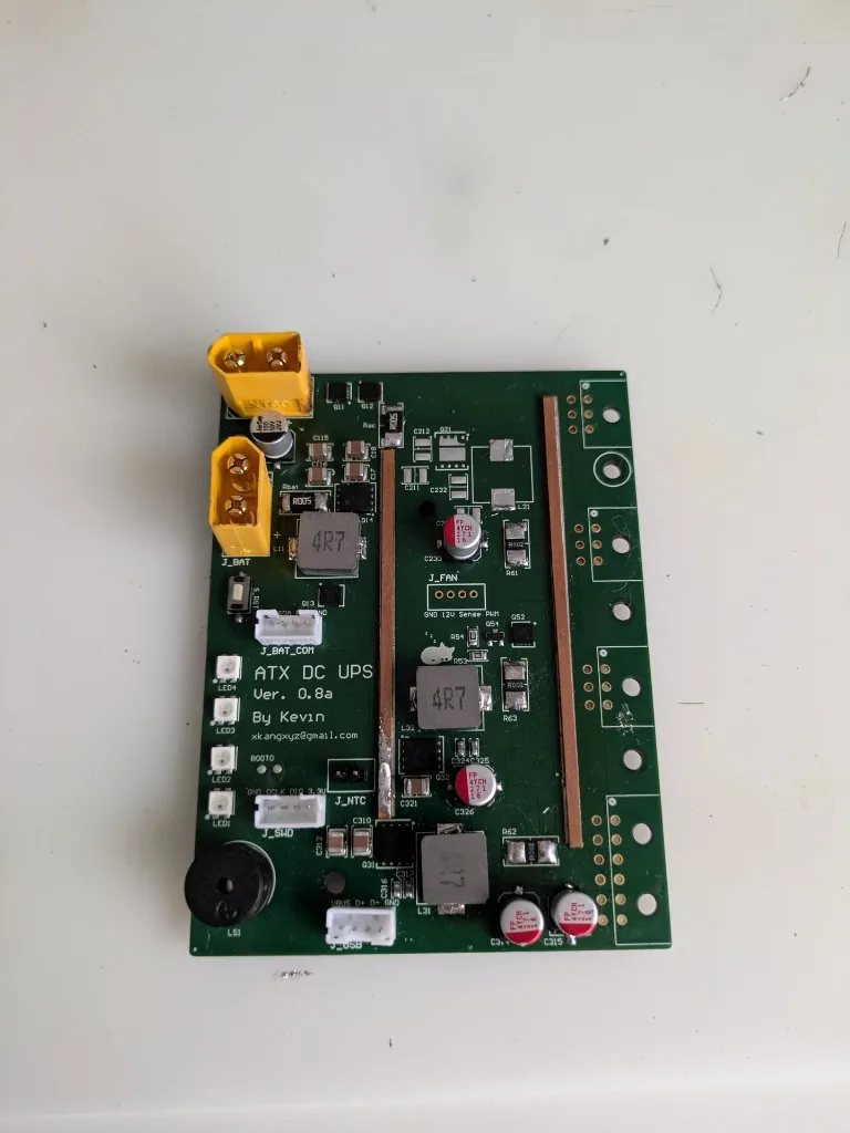
ATX standard-compliant DC Uninterruptible Power Supply (UPS) for desktop computers. Delivers up to 180W output with glitchless zero-latency battery cutover, high-precision 3-rail power monitoring, multi-level safety protections, and USB PC management software.

ENGINEERING DESIGN OVERVIEW

An uninterruptible power supply engineered specifically for PC workstations adhering strictly to the ATX power supply specification. Unlike bulky AC-to-AC UPS units with double conversion losses, this DC-to-DC architecture interfaces directly with the system bus, providing instant battery cutover with zero milliseconds latency when mains drops. Features high-precision 3-rail power monitoring, comprehensive multi-level safety protections (overvoltage, overcurrent, short circuit, and thermal shutdown), and bi-directional USB communication with a dedicated PC host management GUI for real-time AC input power, battery temperature, and individual 4-cell voltage telemetry.

KEY IMPLEMENTATION HIGHLIGHTS

Adheres fully to ATX power timing standards, including proper Power Good (PG) assertion and standby 5VSB rail
Zero-latency power path controller ensuring glitch-free operation for sensitive computer workloads during power cuts
High-precision 3-rail power monitoring (+12V, +5V, +3.3V) with real-time current and voltage telemetry
Comprehensive multi-level safety protections: adapter/battery overvoltage, input/charge overcurrent, short-circuit, and thermal shutdown (TSHUT)
Dedicated PC host management GUI communicating over USB: live monitor for input wattage, 4-cell Li-ion voltages, uptime, and battery health
Reinforced heavy copper busbars hand-soldered directly to PCB power traces to handle up to 180W continuous current with minimal I²R drop

MEASURED HARDWARE SPECIFICATIONS

Max Continuous Power 180W Continuous Output
ATX Rails & Signals +12V, +5V, +3.3V, +5VSB & Power Good (PG)
Switchover Latency 0ms Glitch-Free DC Rail Backup Transition
Power Monitoring High-Precision 3-Rail Voltage & Current Telemetry
Safety Protections Multi-Level (ACOVP, ACOC, CHGOCP, BATOVP, Short, TSHUT)
PC Host Interface USB Telemetry & Smart DCDC UPS Management Software

TECHNOLOGIES & TOOLING

ATX SpecificationDC-DC ConvertersAltium Designer3-Rail Power SensingMulti-Level ProtectionUSB PC GUI4S Li-ion BMSHeavy Copper Busbars

300W MOSFET Electronic Load

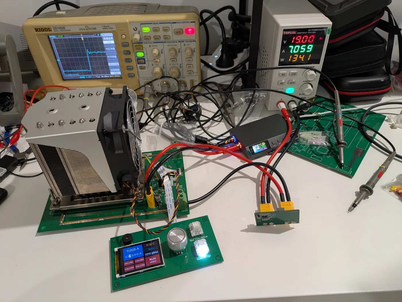
Active 4-MOSFET electronic load instrument supporting up to 300W continuous thermal dissipation. Features fast closed-loop PID current regulation, dynamic transient load step testing, a 3.5-inch LVGL embedded GUI, USB PC host software communication, and intelligent thermal management.

ENGINEERING DESIGN OVERVIEW

A high-power programmable electronic load instrument designed for validating power supplies, battery discharge curves, and DC-DC converters. Operates up to 300W continuous thermal dissipation utilizing 4 parallel linear-mode power MOSFETs mounted to a server CPU tower heatsink. Employs a real-time closed-loop PID algorithm to rapidly regulate sinking current with high precision and evaluate transient step recovery on an oscilloscope. Features an interactive 3.5-inch color display powered by the LVGL embedded graphics library, seamless USB connectivity for PC host management software, and intelligent temperature monitoring.

KEY IMPLEMENTATION HIGHLIGHTS

4-MOSFET parallel linear stage with active thermal balancing and individual shunt current feedback (single-load architecture)
High-speed PID current regulation algorithm eliminating overshoot and settling within microseconds
Dynamic response testing capability for evaluating power supply transient load step stability
Interactive 3.5-inch color display powered by LVGL GUI showing live voltage, current, power, temperature and fan speeds
Bi-directional USB communication with PC host management software for automated logging and remote control
Intelligent thermal monitoring with dynamic closed-loop fan regulation to maintain safe junction temperatures under 300W load

MEASURED HARDWARE SPECIFICATIONS

Power Dissipation 300W Continuous Load Capacity
MOSFET Power Stage 4x Parallel MOSFET Linear Stage with Thermal Balancing
Current Regulation Fast Closed-Loop PID Current Control Algorithm
Embedded Display 3.5-Inch Color Screen with LVGL GUI + Rotary Encoder
PC Host Interface USB Telemetry & Communication with Dedicated PC Host App
Thermal Control Intelligent Thermal Monitoring & Smart Fan Regulation

TECHNOLOGIES & TOOLING

4x Power MOSFETsPID AlgorithmLVGL Embedded GUI3.5" DisplayUSB PC Host AppSmart Thermal MonitoringDynamic Load StepOscilloscope Analysis

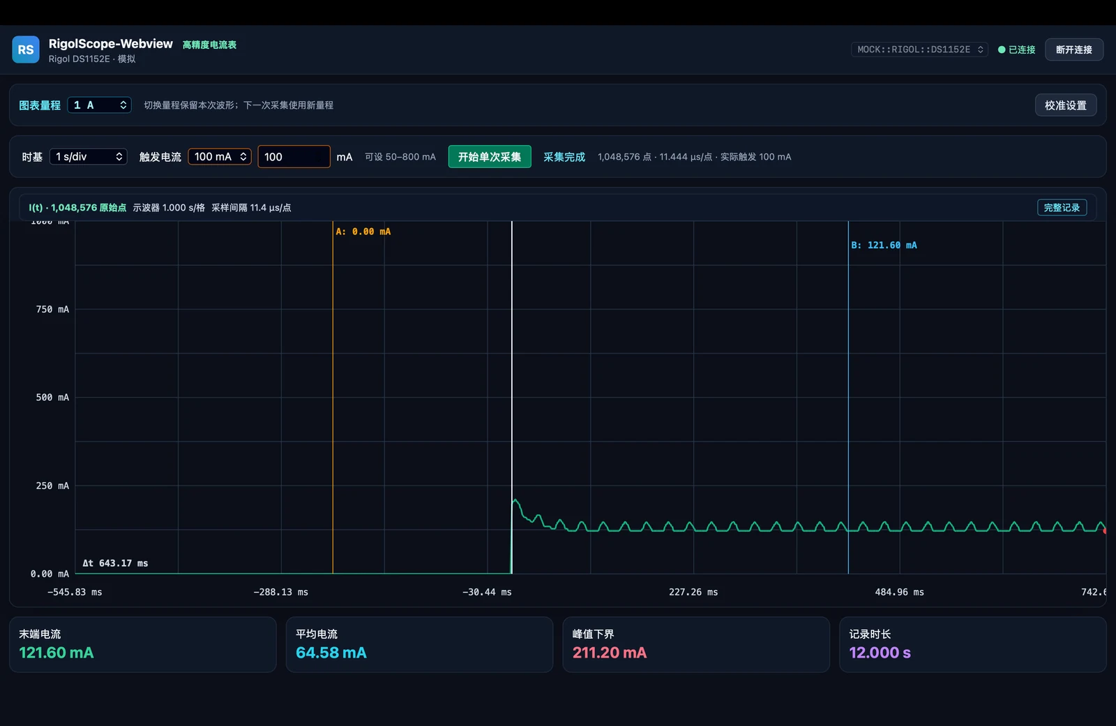
RigolScope-Webview: Oscilloscope Precision Current Meter

Oscilloscope-based high-precision current measurement system utilizing a custom sampling PCB with INA190A1 amplification, digitized via Rigol DS1152E oscilloscope, and connected to a PC host webview GUI with adjustable timebases, measurement ranges, and trigger currents.

ENGINEERING DESIGN OVERVIEW

An end-to-end hardware-software instrumentation tool for capturing micro-current transients and dynamic power profiles. Front-end sampling is performed by a custom-designed PCB utilizing Texas Instruments INA190A1 high-precision current sense amplifier. The amplified analog signal is acquired by a Rigol DS1152E digital storage oscilloscope and streamed to a custom PC host webview application via SCPI/USBTMC commands. Users can adjust timebases, select ranges (e.g. 1A, mA scales), and set trigger thresholds.

KEY IMPLEMENTATION HIGHLIGHTS

Engineered custom current sampling PCB with precision shunt resistor and INA190A1 low-offset amplifier
Automated SCPI protocol communication with Rigol DS1152E oscilloscope over USBTMC for waveform extraction
Designed modern PC webview host application displaying real-time current curves, average current, peak values, and duration
Configurable interactive controls: timebase adjustments, gain ranges, and real-time current trigger levels

MEASURED HARDWARE SPECIFICATIONS

Front-End Sampling Custom PCB with INA190A1 Precision Current Sense Amplifier
Acquisition Engine Rigol DS1152E Digital Storage Oscilloscope (SCPI/USBTMC)
PC Host Interface Custom Modern Webview GUI with Real-time Charting
User Adjustments Configurable Timebase (s/div), Measurement Range & Trigger Current

TECHNOLOGIES & TOOLING

INA190A1Rigol DS1152E DSOCustom Sampling PCBSCPI / USBTMCPC Webview GUISignal AmplificationJavaScript/Frontend
DIAGNOSTIC & REWORK WORKBENCH

Built with Industrial-Grade Benchtop Equipment

Every PCB, power converter, and prototype showcased here was designed, hand-soldered, inspected under stereo microscopes, and characterized using Kevin's private hardware lab in North Lakes, QLD.

Tour Kevin's Diagnostic Lab